Here is a sequence of photos showing the construction of a Miller Solar Engine using all SMD parts. I have used Bostik Blu-Tak to hold the parts while soldering. I have chosen to use a FET for several reasons. Using a FET instead of a normal transistor means that you can eliminate the current limiting resistor on the base of the transistor - less parts! It makes a good base for building the SE on. And the output pins on finished assembly can easily connect to the enable pins of a 74AC240 chip when placed directly on top.
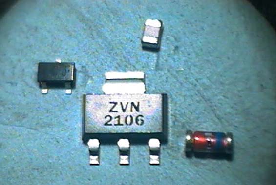
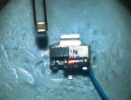
MN1382-J , ZVN2106G, Case 0805 Cap .22Uf 16v, MiniMelf Diode
Bend gate lead around to top of chip.
Slide pin 1 of 1382 under gate and solder.
Apply a small amount of solder to pin 3 of the 1382.
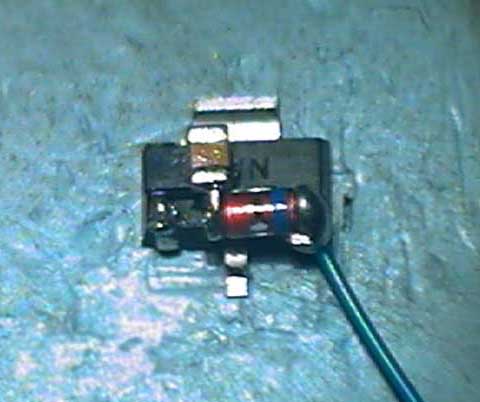
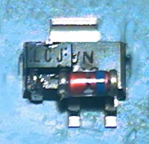 Solder anode of diode to pin 3 of the 1382
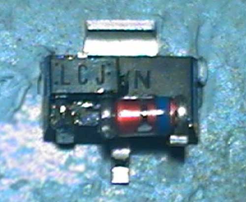 Bend source pin up to meet cathode of diode.
 End view of diode cathode.
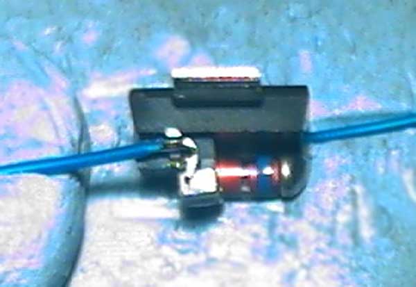
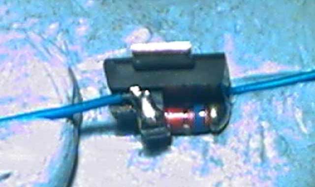
 Strip wire and bend end - insert into gap.
 Solder.
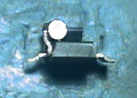
 Use tweezers to place capacitor on top of 1382.
 Solder capacitor to edge of diode anode.
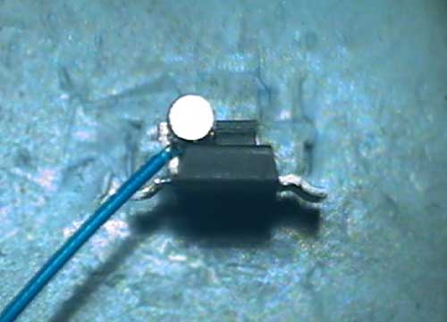
 Strip wire and form a small hook in the end, rotate assembly so you are looking down at the top.
 Use Bostik Blu-Tak to hold wire across cap and pin 2 of the 1382 and solder.
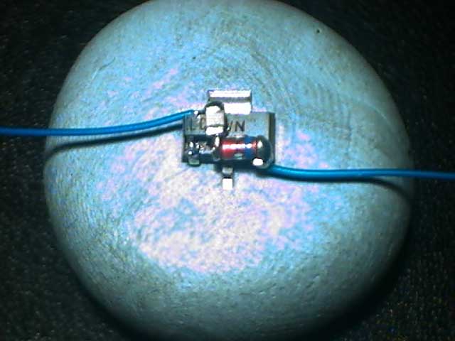 Here is the SE before re-soldering the joints quickly one at a time - for a good finish.
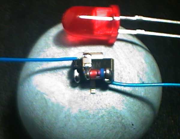 Finished SMD-SE after cleaning with a toothbrush under water to remove the HydroX solder flux (5mm FLED for size comparison).
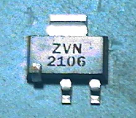
 Zetex ZVN2106G connection diagram.
 Panasonic MN 1382 connection diagram.
© Neil Sandstrom 2003